
Science with Passion
Application No.: VTN0010 Version 1 10/2020
Streamlining of equipment: Hybrid system for preparative and analytical LC
Lisa Loxterkamp, Johannes Menke, Kate Monks; applications@knauer.net
KNAUER Wissenschaftliche Geräte GmbH, Hegauer Weg 38, 14163 Berlin

Photo: KNAUER
Summary
When separating and purifying molecules by liquid chromatography (LC), it is necessary to develop the method with a preparative high-performance liquid chromatography (HPLC) system. The purification process is often verified for quality and quantity of the products by analytical HPLC. In this case, two LC systems, a preparative and an analytical, are needed for a purification process and the following analysis. In this technical note a combination of these two systems is shown. It describes in detail the system set up and the different method steps. The system is capable of isolating a single substance from a mixture and afterwards performing an automated purity analysis. For proof of concept, caffeine was purified from paracetamol and analysed within the same system.
Introduction
Looking at the major cost generated by chromatography separation techniques, hardware costs are besides the stationary and mobile phase an important factor[1]. Especially in the preparative field, where high flow rates are applied, the eluent costs are not to be neglected. Reducing these costs by combining two systems into one can be beneficial. Another advantage for streamlining systems is the time saved by automating the process. Especially if the process is repetitive, the methodical effort is worthwhile. The aim is to establish a combination of semi-preparative purification in the flow rate range up to 50 ml/min with simultaneous analytical qualification and quantification in one system using the same chromatography software suite. This combination was carried out with the new KNAUER assistant ASM 2.2L, a modular docking station combining several valves. With two multi-position 6 port valves, up to three different columns can be used in this system to perform a method development or to purify different compounds in a semi-preparative scale. With two injection valves, sample introduction for preparative or analytical purposes can be introduced in the system separately. The purification step is carried out with a KNAUER VariLoop L, where up to 40 ml sample can be stored. The VariLoop is a storage container which can be filled in only one direction and drained in the opposite direction. The two sites are separated by an integrated pressure valve passing eluent in one direction for flushing.
Its purpose is to separate a flexible amount of volume without mixing the fraction further with eluent. For eluent delivery a KNAUER P6.1L HPG pump with 50 ml pump head was used. A multi-wavelength UV detector with a pressure proof 10 µl flow cell with 10 mm path length was used for detection. Within this work a KNAUER Eurospher C18 150x20 mm ID preparative column with 10 µm particle size was used for the example separation of caffeine and paracetamol. For the analytical verification of the caffeine content the Eurospher C18 150x4 ID with 5 µm particle size was used. For system control ClarityChrom 8.2 was employed. The established system shown here, can support the first stages for optimization of the method as well as scale up for the process with different column dimensions[2].
Results
In Fig. 1 the flowpath of the system and the different valve positions are shown and described. The system flow starts from the bottom at the P 6.1L and passes through the first ASM 2.2L towards the columns followed by the MWD 2.1L. Depending on the VariLoop load valve setting the sample goes either to waste or is collected in the VariLoop for fractionation and analysis.

Fig. 1 The used system with the different components and modules.
VariLoop unload: A 2-position 6 port valve is delivering eluent towards the columns in position 2 and unloads the VariLoop in position 1.
Preparative Injection: A 2-position 6 port valve is used for preparative injection where position 1 loads the sample and position 2 injects it.
Analytical injection: A 2-position 8 port valve, contains two similiar loops and loads the sample in position 2 and injects it in position 1 in the manual injection method. During the continuous run, position 1 is default and position 2 loads the sample in the other loop.
Multi-position in is marked as the multi-position 6 port valve where position 1 is connected to the bypass. Position 4 is the analytical and position 5 is the preparative column. Additionally position 2 leads to the waste and position 3 is for fractioning. The two multi-position valves are switched simultaneously.
Multi-position out is marked as the multi-position 6 port valve where position 1 is connected to the bypass. Position 4 is the analytical and position 5 is the preparative column. The two multi-position valves are switched simultaneously.
VariLoop load: A 2-position 6 port valve is loading the 40 ml VariLoop in position 1 and unloading it in position 2.
The purification and analysis were divided into six methods:
Step 0 - „Scouting“ is intended for determining the fractionation time of the target component.
Step 1 - „Purification“ represents the actual purification step in which the sample is separated on the preparative column and the target fraction collected into the VariLoop.
Step 2 - „Unload“ unloads the target fraction from the VariLoop into the desired storage container. Meanwhile an aliquot is taken and filled into the analytical sample loop.
Step 3 - „Equilibration“ is the equilibration of the analytical system and column.
Step 4 - „Analysis“ is the actual analysis of the stored fraction aliquot in the analytical loop.
Step 5 - „Manual analysis“ is the manual injection of the fraction or can be used when quantifying the sample after the original run. All method parameters are documented in the „Materials and Methods“ part.
Combining the above mentioned methods and valve positions, Fig. 2 shows an overview of the given system flow. The valve changing process is documented in a video (see QR code below). The detailed time switching valve positions are documented in the tables in chapter „Materials and methods“.
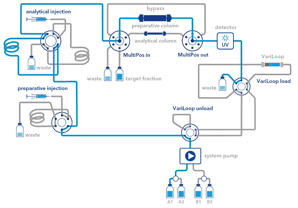
Fig. 2 Flowchart overview for the scouting and purification step.

Sample preparations
Sample preparation: 101.5 mg paracetamol and 148.6 mg caffeine were dissolved in a 10 ml volumetric flask containing 20:80 ethanol/water (v/v). After complete dissolution, 20% ethanol was added to the mark and the sample was filtered through a 0.45 µm RC filter. The solution corresponded to a concentration of 10.15 mg/ml paracetamol and 14.86 mg/ml caffeine. This solution was used for the purification experiments. For the calibration 14.2 mg caffeine were dissolved in a 10 ml volumetric flask with 20% EtOH. After complete dissolution, 20% EtOH was added to the mark and the sample was filtered through a 0.45 µm RC filter. From this stock solution 1 ml was diluted to 10 ml with 20% EtOH (calibration level L3). For calibration level L2, 0.5 ml of the stock solution was diluted to 10 ml 20% EtOH. For calibration level L1, 100 µl of the stock solution were diluted to 10 ml 20% EtOH. The resulting concentrations are shown in Tab. 1.
Tab. 1 Calibration dissolution, concentration stock solution 1.42 mg/ml
Calibration level | Dilution ratio | Concentration (µg/ml) |
L1 | 1:100 | 14.2 |
L2 | 1:20 | 71.0 |
L3 | 1:10 | 142.0 |
Fractioning and calibration: In Fig. 3 the chromatogram shows the two signals of paracetamol and caffeine with the given fractionation window backed green. Fig. 4 compares the area of caffeine with the automated and manual analysis of the fraction. During the manual fraction analysis, carry-overs were detected which disappeared after three blank injections. At low concentrations of the analyte, the effect is less pronounced and one blank injection between each analyte injection is sufficient.
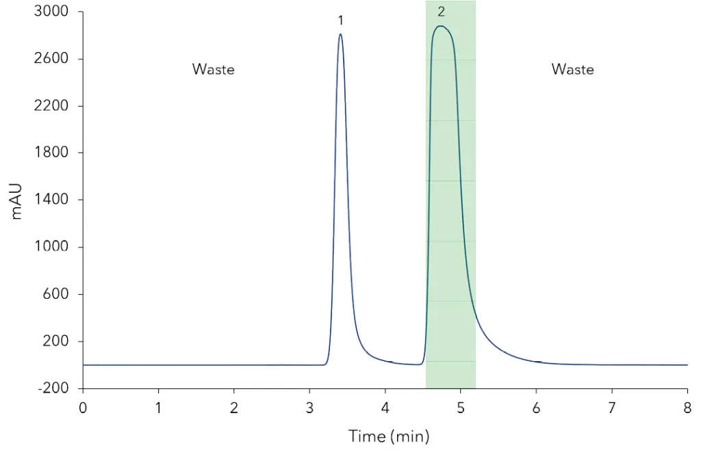
Fig. 3 Step 1 Purification with fractionation window (green), 50 µl injection, 15 ml/min flow. 1 - Paracetamol, 10 mg/ml; 2 - Caffeine, 15 mg/ml.

Fig. 4 1 - Step 4 Automated analysis, 10 µl injection, 1 ml/min flow, caffeine area: 2807,6 mAU∙s. 2 - Step 5 Manual analysis of the fraction from Fig. 2,
10 µl injection, 1 ml/min flow, caffeine area: 2283,6 mAU∙s.
Fig. 5 and Tab. 2 show the results of the calibration compared to the measured samples. The comparison of the automated fraction analysis of step 4 and the manual fraction analysis of Step 5 shows a caffeine concentration of 88.7 µg/ml to 72.4 µg/ml or 2807.6 mAU∙s to 2283.6 mAU∙s. The originally added concentration of caffeine corresponded to an absolute concentration of 82.6 µg/ml (15.2 mg/ml caffeine sample, 50 µl injection volume and 9.2 ml VariLoop fraction volume). The L1 standard with 10 µg/ml showed a signal-to-noise ratio of about 120 (peak height: 33.6 mAU, noise (ASTM) 0.2811 mAU (from 0.4-2.8 min)).
Tab. 2 Calibration results
Calibration Level | Concentration (µg/ml) | Area (mAU∙s) |
L1 | 14.2 | 431.69 435.06 |
L2 | 71.0 | 2208.25 2222.46 |
L3 | 142.0 | 4539.04 4514.57 |

Calibration function Y=32.05*X-35.53
Correlation coefficient R=0.99995
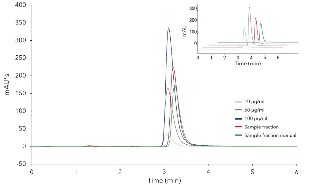
Fig. 5 Calibration standards compared to samples.
Conclusion
It is possible to combine a semi-preparative purification of paracetamol and caffeine with simultaneous qualification of the fraction within 26 minutes. Furthermore, additional manual injections for the analytical determination can be performed using an 8 port 2-position injection valve with two similar loops. This allows a direct quantification of different samples independent from the collected fraction. The collected caffeine fraction in the analytical loop at step 4 shows a higher concentration of 88.7 µg/ml than the manual determination in step 5 with 72.4 µg/ml. Taking into account that only a time window of six seconds was used for analytical sampling, the sample is representative. Compared to the absolute injection concentration of 82.6 µg/ml, the step 4 sample with 88.7 µg/ml is higher. This might indicate that the fraction was not sufficiently mixed in the VariLoop, thus resulting in an inhomogenous concentration distribution. When injecting manually, it can be assumed that the mixing in the fraction container was complete. Since the fraction (40 s fraction collection to 1.2 min peak width) does not contain the complete caffeine peak either, the concentration of 72.4 µg/ml seems more realistic. In percentage terms this corresponds to approximately 88% of the initial concentration. Nevertheless, the sample is diluted during the preparative run. Previously, overloading with caffeine resulted in a signal intensity of 2 500 mAU compared to the approximately 200 mAU of the analytical determination. This ten times signal dilution of the analytical run must be considered when lower sample concentrations are injected at the beginning. The two multi-position 6 port valves have one additional port to use with another column to test different purification methods. It is also possible to switch to 8 or 16 multi-positions valves. With the HPG pump it is possible to connect four different eluents, which makes flexible solvent choice and method development possible. However, the flow rate should be checked in the small flow range of less than 1 ml/min. Using flow rates below 1 ml/min the solvents should be mixed beforehand if necessary. Otherwise, insufficient mixing and thus strong baseline fluctuations are to be expected. A maximum pressure of 300 bar restricts the system on an analytical scale in the choice of particle size. In this case a stationary phase material with 5 µm particle was used instead of a 3 µm particle, to prevent high back pressure. The valve control with ClarityChrom 8.2 is time based and therefore needs to be adapted according to every change in the system, otherwise back pressures from over 300 bar can occur easily. Taking into account these limitations a preparative purification with subsequent analysis of the purified product can be automized within one HPLC system to save time and resources.
Materials and Methods
Tab. 3 Analytes
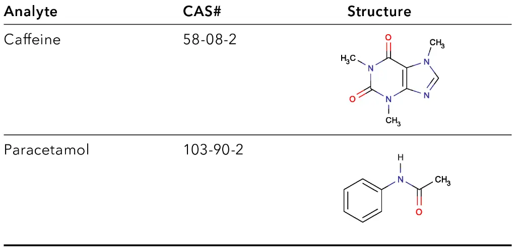
Tab. 4 Method

Step 1 - Purification

Step 2 - Unload
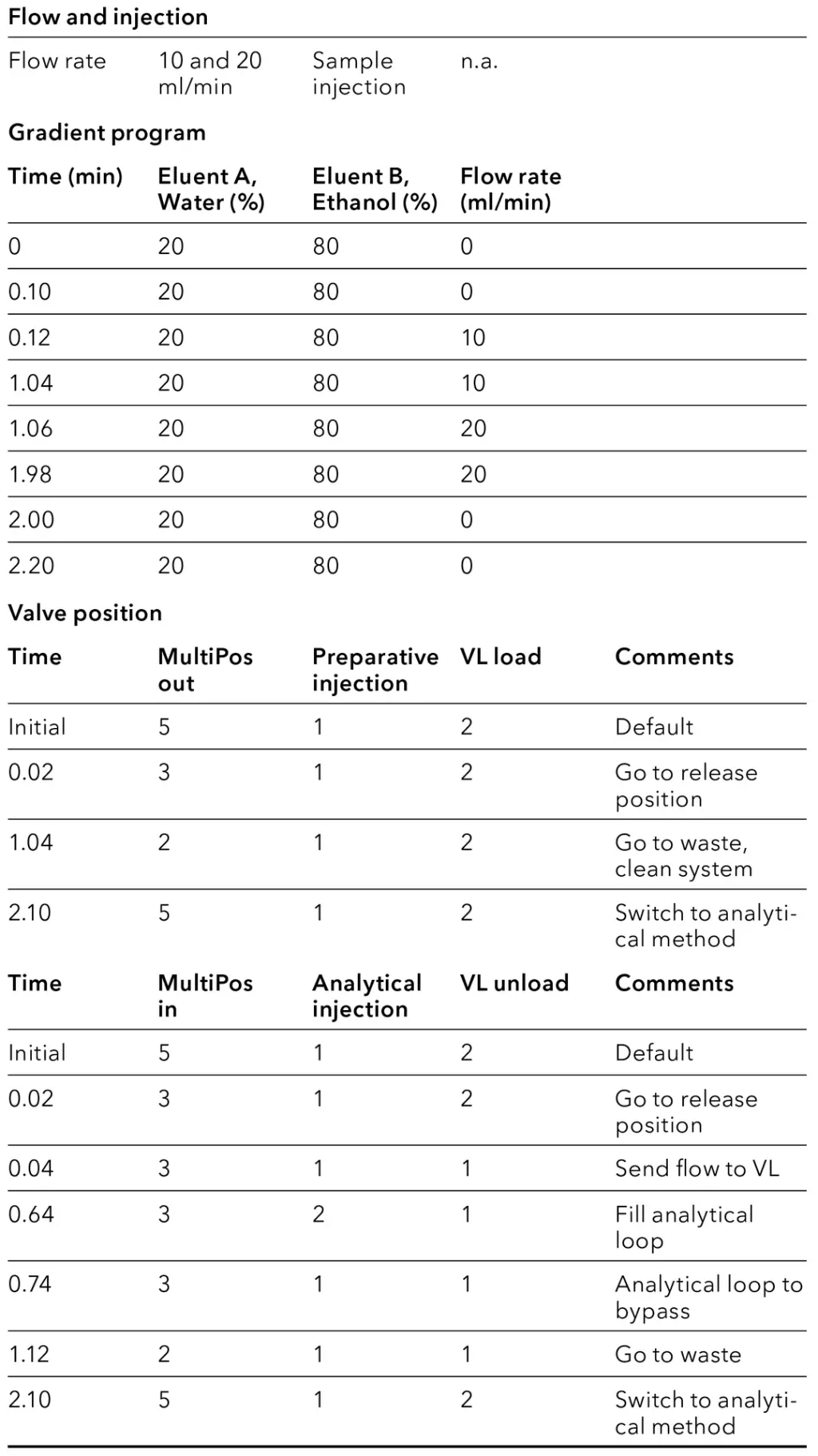
Step 3 - Equilibration

Step 4 - Analysis

Step 5 - Manual Analysis

Materials and Methods
Tab. 5 System configuration
Instrument | Description | Article No. |
Column | Preparative column, Eurospher II 100-10 C18, column 150x20 mm | |
Column | Analytical column, Eurospher 100-5 C18 with precolumn, column 150x4 mm | |
Preparative sample loop | 40 ml KNAUER VariLoop L for 1/16" tubings | |
Software | ClarityChrom 8.2 - Workstation, autosampler control included | |
Detector | AZURA Detector MWD 2.1L, 190-700 nm, multiwavelength detector | |
Flow cell | Analytical KNAUER PressureProof UV flow cell cartridge | |
Pump | AZURA P 6.1L high pressure pump with 50 ml pump head, stainless steel, without degasser | |
Assistant top | AZURA Assistant ASM 2.2L | |
Valve drive (left) (Multiposition out) | AZURA V 4.1 Valve with multiposition valve, 6 Port, sst, 1/16”, 500 bar, 0.75 mm bore size | |
Valve drive (middle) (Preparative injection) | AZURA V 4.1 Valve with 2-position valve, 6 Port, sst, 1/16”, 500 bar, 0.75 mm bore size | |
Valve drive (right) (VariLoop load) | AZURA V 4.1 Valve with 2-position valve, 6 Port, sst, 1/16”, 500 bar, 0.75 mm bore size | |
Assistant bottom | AZURA Assistant ASM 2.2L | |
Valve drive (left) (Multiposition in) | AZURA V 4.1 Valve with multiposition valve, 6 Port, sst, 1/16“, 500 bar, 0.75 mm bore size | |
Valve drive (middle) (Analytical injection) | AZURA V 4.1 Valve with 2-position valve, 8 Port, DLC, sst, 1/16“, 500bar, 0.75 mm bore size | |
Valve drive (right) (VariLoop unload) | AZURA V 4.1 Valve with 2-position valve, 6 Port, sst, 1/16“, 500 bar, 0.75 mm bore size |
References
[1] Schmidt-Traub, H., Schulte, M., Seidel-Morgenstern, A. Preparative Chromatography (second edition). Wiley-VCH Verlag & Co. KGaA. (2012).
[2] Aldington, S., Bonnerjea, J. Scale-up of monoclonal antibody purification processes. Journal of Chromatography B, 15;848(1):64-78 (2007).
Application details
|
Method |
Preparative and analytical HPLC |
|
Mode |
RP |
|
Substances |
Paracetamol, caffeine |
|
CAS number |
Paracetamol: CAS 103-90-2; Caffeine: CAS 58-08-2 |
|
Version |
Application No.: VTN0010 | Version 1 10/2020 | ©KNAUER Wissenschaftliche Geräte GmbH |


