Science with Passion
Application No.: VTN0046 Version 1 11/2025
Understanding system peaks in GPC/SEC for accurate and reliable analysis
J. Wesolowski, J. Kramer, U. Krop, K. Folmert; wesolowski@knauer.net
KNAUER Wissenschaftliche Geräte GmbH, Hegauer Weg 38, 14163 Berlin

Graphic: KNAUER
Summary
In liquid chromatography (LC), system peaks (SPs) are extra signals caused by temporary disturbances to the equilibrium between the mobile and stationary phase. Reliable analysis of chromatographic data requires the identification of these system peaks. Here, two approaches are demonstrated for this purpose: first, overlaying the chromatogram of a blank injection with that of a sample injection, and second, spiking the mobile phase with its individual components to clearly assign each system peak.
Introduction
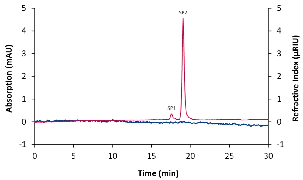
In liquid chromatography (LC), it is common that chromatograms show more peaks than can be directly assigned to the analytes [1] [2]. These additional signals, known as system peaks (SPs), occur when the equilibrium between the mobile and stationary phase is temporarily disrupted, for example during sample injection [1]. In Gel Permeation Chromatography/Size Exclusion Chromatography (GPC/SEC), system peaks typically appear at the end of the chromatogram, indicating the transition from size-based (entropy-driven) to interaction-based (enthalpy-driven) separation [3]. Universal detectors, such as the refractive index (RI) detector, make these effects clearly visible even when pure mobile phase is injected (Fig. 1) [3].

Fig. 1 Chromatogram of a 20 µL blank injection using column coupling. Blue: diode array detector (DAD) at 230 nm; red trace: RID.
System peaks can appear as positive or negative signals, and while their retention time is generally constant, their peak shape, height and area depend strongly on the composition and amount of the injected sample [3]. Therefore, a system peak should not be used as a flow marker in GPC/SEC (see VTN0043 for more details about the use of a flow marker in GPC/SEC analysis). To minimise system peaks, samples should be dissolved in the mobile phase that is used for analysis, small injection volumes should be used, and adequate equilibration time before measurement should be ensured [3]. However, it is not possible to completely avoid system peaks. Therefore, it is essential to identify them to correctly analyse the data, as they can overlap with analyte peaks and alter their peak shape, which may lead to misinterpretation. Comparing a blank injection with a sample injection enables system peaks to be clearly identified [1] [2]. Furthermore, injecting the individual mobile phase components can help to assign the peaks [3].
Sample Preparation
The used mobile phase was phosphate-buffered saline (PBS, pH 7.4, from Sigma-Aldrich). Individual standards of ethylene glycol and citric acid were prepared in PBS and filtered through a 0.45 µm cellulose acetate (CA) filter. These substances were selected as representative test analytes to demonstrate system peaks. The components of the PBS buffer solution (sodium chloride, potassium chloride, potassium dihydrogen phosphate and disodium hydrogen phosphate) were also prepared as single standards. Furthermore, a PBS blank was prepared and filtered in the same way to account for systematic effects.
Results
Fig. 2 shows an exemplary chromatogram of an aqueous SEC analysis. When injecting citric acid, two small peaks were detected by the RI detector (orange trace). In comparison, ethylene glycol generated three peaks (pink trace). The blank injection showed two small peaks (black trace). Overlaying the blank and the two sample chromatograms allows clear identification of the two system peaks (SPs). Here the system peaks appear as positive signals with constant retention times, while their height and area differ between the chromatograms depending on the composition of the injected sample. In the case of citric acid, only two peaks are observed instead of the expected three. This is because the first system peak (SP 1) elutes at the same time as the citric acid peak, causing a slight shoulder on the analyte signal. This highlights the importance of considering system peaks during data evaluation to avoid misinterpretation.

Fig. 2 Overlay chromatograms measured with RID, 20 µL injection volume and column coupling. Orange: citric acid; pink: ethylene glycol; black: blank.
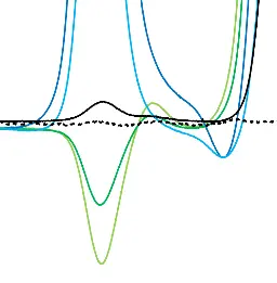
To better understand which peak originates from which component of the mobile phase, each additive was prepared separately and individually spiked to the mobile phase before being analyzed using the SEC system. The results are shown in Fig. 3. The PBS blank injection from Fig. 2 (black trace) is compared with injections containing sodium chloride (light green), potassium chloride (dark green), potassium dihydrogen phosphate (light blue), and disodium hydrogen phosphate (dark blue). This allows you to gain a deeper understanding of system peaks and can also help you to optimise the method by adjusting the buffer salts or concentrations.

Fig. 3 Overlay chromatograms measured with RID, 20 µL injection volume and column coupling. Black: blank; light green: sodium chloride; dark green: potassium chloride; light blue: potassium dihydrogen phosphate; dark blue: disodium hydrogen phosphate.
Conclusion
System peaks are caused by temporary disturbances to the chromatographic equilibrium, typically appearing at the end of GPC/SEC chromatograms. They can be minimised through proper sample preparation, small injection volumes and stable system conditions, but they cannot be completely eliminated. Therefore, it is crucial to identify system peaks by comparing blank and sample measurements or by analysing the individual mobile phase components to ensure reliable evaluation of the chromatographic data.
Material and Methods
Tab. 1 Method parameter.
Parameter | Value |
Flow rate | 1 mL/min |
Mobile phase | H2O/PBS-Buffer (pH 7.4) |
Column temperature | 30 °C |
Injection volume | 20 µL |
Injection mode | Partial loop |
Wavelenght | 230 nm |
Data rate | 10 Hz |
Time constant | 0.1 s |
Time | 30 min |

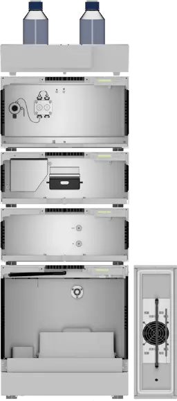
Fig. 4 SEC system setup.
Tab. 2 System configuration.
Instrument | Description | Article No. |
Pump | AZURA® P 6.1L Pump Isocratic, Stainless Steel, 10 ml/min, without Degasser | |
Detector | AZURA® RID 2.1L Refractive Index Detector with Flow Cell, up to 10 ml/min | |
AZURA® DAD 6.1L Diode Array Detector with Test Cell, without Flow Cell, | ||
UV Flow Cell Cartridge, PressureProof, Analytical, 10 mm, 10 µL, Titanium, 1/16”, 300 bar, up to 20 ml/min | ||
Autosampler | AZURA® AS 6.1L analytical Autosampler up to 1240 bar, without cool/heat option | |
Thermostat | AZURA® CT 2.1 Column Thermostat for up to 8 HPLC columns with temperature range between 5–85 °C | |
Column coupling | AppliChrom SuperOH-P-150, 7 μm, 300 x 8 mm SEC Column, Separation range 100–5000 Da | |
AppliChrom SuperOH-P-350, 10 µm, 300 x 8 mm SEC Column, Separation range 2500 Da–1000k Da | ||
Capillaries | AZURA® Analytical MarvelXACTTM StartUp kit for HPLC Set of capillaries, adapters and connectors | |
Software | ClarityChrom® 9.1.0 station single instrument license one time base | |
ClarityChrom® 9.1.0 GPC license for GPC data processing |
References
[1] Srbek J., Coufal P., Bosáková Z. & Tesařová E. (2005). System peaks and their positive and negative aspects in chromatographic techniques. Journal Of Separation Science, Vol. 28 (12), 1263 - 1270.
[2] Levin S. & Grushka E. (1986). System Peaks in Liquid Chromatography: Their Origin, Formation, and Importance. Analytical Chemistry, Vol. 58 (8), 1602 - 1607.
[3] Held D. & Gores F. (2019). Tips & Tricks GPC/SEC: System Peaks or Ghost Peaks in GPC/SEC. LCGC International. https://www.chromatographyonline.com/view/tips-tricks-gpcsec-system-peaks-or-ghost-peaks-gpcsec (Last access: 10.10.2025).
Application details
|
Method |
GPC/SEC |
|
Mode |
GPC/SEC |
|
Substances |
Ethylene glycol, citric acid, sodium chloride, potassium chloride, potassium dihydrogen phosphate, disodium hydrogen phosphate |
|
CAS number |
107-21-1, 77-92-9, 7647-14-5, 7447-40-7, 7778-77-0, 7558-79-4 |
|
Version |
Application No.: VTN0046 | Version 1 11/2025 | ©KNAUER Wissenschaftliche Geräte GmbH |


