
Science with Passion
Application No.: VTN0014 Version 1 12/2020
Two step purification with a basic set up
Ulrike Krop, Kate Monks; applications@knauer.net
KNAUER Wissenschaftliche Geräte GmbH, Hegauer Weg 38, 14163 Berlin
What is two step purification?
Two step purification is a special multicolumn chromatography solution. Two independent methods, each with their associated specific column, are used to realize the purification of the target molecule without manual interference. The principle here is that the protein sample is applied on the first column. During elution of the protein, the protein peak is detected triggering the collection of the eluted protein in a storage loop or storage vessel/container. The protein is then automatically applied on the second column to further enhance the quality and or purity of the purified protein. Several system set ups can be used to automate the purification. In this TechNote a Two step purification with a basic set up is discussed.
Basic system set up: What do i need?
In the basic set up a Lab standard KNAUER Multi Method FPLC system for all biochromatography methods is adapted. Next to the column selection valve and the outlet valve no other components must be added to the system (Fig. 1).
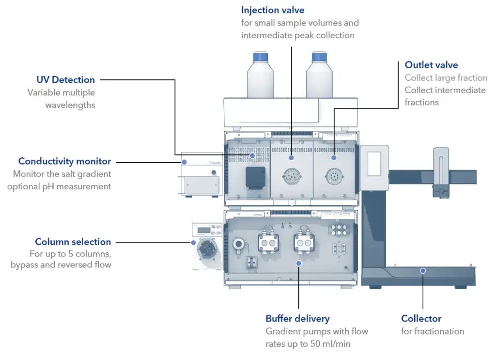
Fig. 1 AZURA Bio Lab system in basic set up: Exemplary configuration for automated two step applications.
In the basic two step set up the sample is injected via the sample loop of the injection valve. The first peak is collected as well in the sample loop of the injection valve and redirected to the second column. This set up is limited to small sample volumes. The volume of the elution peak of the first column should be equal or even smaller than the injection volume due to diffusion effects that will result in sample loss (Fig. 2).
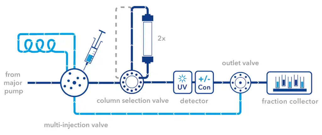
Fig. 2 Flow scheme for the basic set up for two step purification.
The column selection valve is placed between the multi-injection valve and the UV detector. The column outlet port (Col) of the multi-injection valve is connected via the PEEK capillary with the inlet port (IN) of the column selection valve. The outlet port (OUT) is the connected to the UV detector flow cell which in turn is connected to the conductivity monitor. The columns are installed according to Fig. 3.
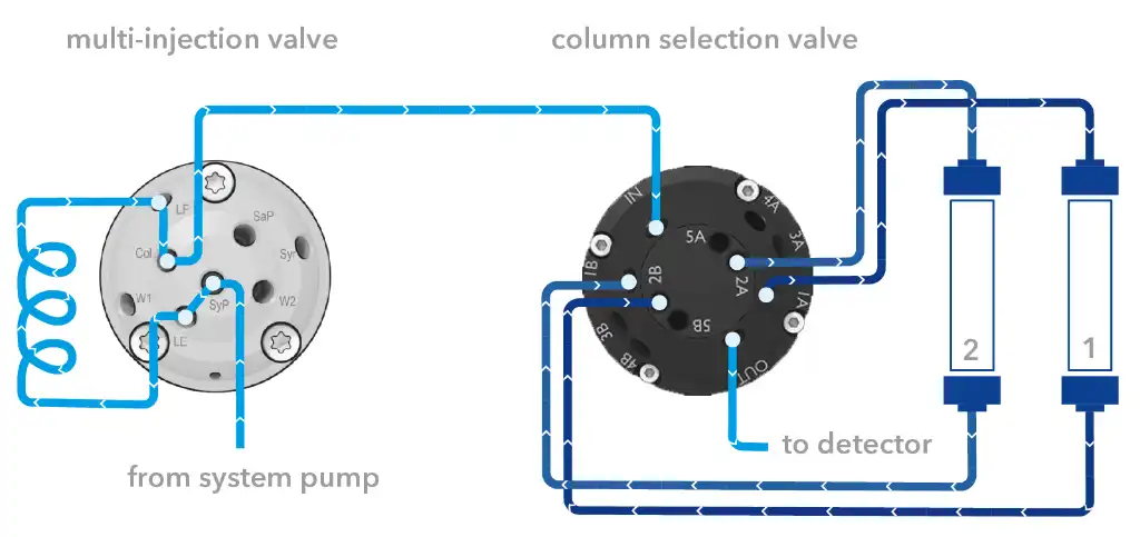
Fig. 3 Connection of the column selection valve.
The outlet valve is placed between the conductivity monitor and the fraction collector. The conductivity monitor is connected via the PEEK capillary with the middle port of the outlet valve. Port 1 of the outlet valve goes by default to the fraction collector or waste container. Port 3 to 8 can be used for the collection of large fractions. Port 2 (reinjection) of the outlet valve is connected to the sample pump port (SaP) of the multi-injection valve (Fig. 4) The syringe port is still accessible for sample injection.
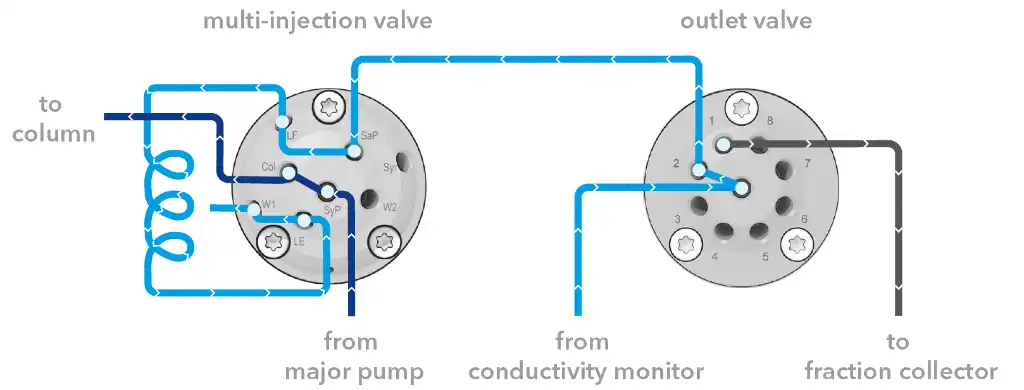
Fig. 4 Connection of the outlet valve.
The set up is, due to the use of the same sample loop for injection and reinjection, limited to small sample volumes. To overcome the problem of the small sample volume a variation of this set up is to inject the sample via the major pump. For this set up some additional changes must be implemented. The filter cartridge of the pressure sensor must be replaced by a dummy. Please follow the manual for exchanging the pressure filter. When exchanging the pressure filter, we strongly advise to install an inline filter in front of the column selection valve (Fig. 3). The filters frits of the inline filter should be cleaned or replaced from time to time. Additionally, the sample should be filtered via a 0,45 µm filter before injection.
How to write a method
In the following section we will describe how to write an exemplary method for two step purification with PurityChrom. See also our Checklist: „Creating methods in PurityChrom®“ in the PurityChrom Installation Information. In our example in the first step a 1 ml ion exchange column and in the second step a 5 ml desalting column was used. A 2 ml sample loop was used for sample injection and intermediate peak parking. Two separate methods were written for the two columns. First, important aspects of the ion exchange method are highlighted for the time control file (Fig. 5 to 7A) and the changes in the flow are depicted in the flow scheme/visualization (Fig. 5 to 7B). Make sure to choose the correct column in the beginning of the method (Fig. 5, 1). The sample is inserted in the manual load configuration of the multi-injection valve. During injection, the multi-injection valve switches to the inject position (Fig. 5, 2).
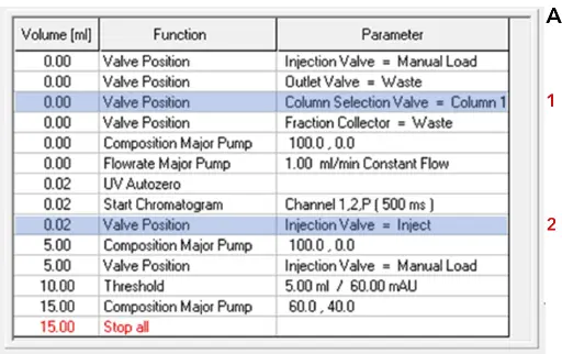

Ion exchange method during injection of sample Time control file of ion exchange method (A). Visualization of AZURA Bio Lab system in basic set up (B).
After the sample injection and an isocratic washing step, the elution starts after 5 ml with beginning of the gradient (Fig. 6A, 1). At this time point the multi-injection valve should be switched back to the manual load position (Fig. 6, 2).
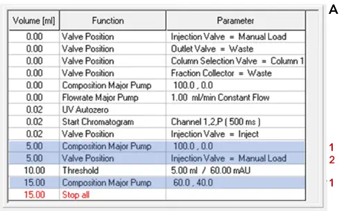

Ion exchange method during gradient elution. Time control file of ion exchange method (A). Visualization of AZURA Bio Lab system in basic set up (B).
To recognize the eluting peak a threshold function is used. The threshold is active during the gradient elution (Fig. 7A). Once a peak above 60 mAU is detected (threshold over event), this peak is rerouted to the sample loop. For this the outlet valve switches to the reinjection position (Fig. 7, 2) and the multi-injection valve switches to pump load (SaP Load) (Fig. 7, 1). If the peak is below 60 mAU (threshold under event) the outlet valve switches back to waste and the multi-injection valve back to manual load. Please keep in mind to program an execution delay in the PurityChrom set up for the delay volume between the UV detector and the outlet valve. At the end of the run purified protein is stored in the injection loop and can be further purified via the second column in the next step without manual interference.


Ion exchange method during collection of the intermediate peak. Time control file of ion exchange method definition of threshold function (A). Visualization of AZURA Bio Lab system in basic set up (B).
The time control file for the second method (Desalting) is shown in Fig. 8A and the flow scheme/visualization is shown in Fig. 8B. Here, the buffer (Fig. 8, 1) and the column changes (Fig. 8, 2). To inject the intermediate peak onto the desalting column the multi-injection valve is set to the inject position (Fig. 8, 3). The eluting peak is precisely fractionated with the help of the threshold function (Fig. 8, 4) using the fraction collector. At the end of the two step purification run the protein is purified and collected in small fractions.
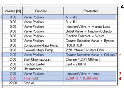
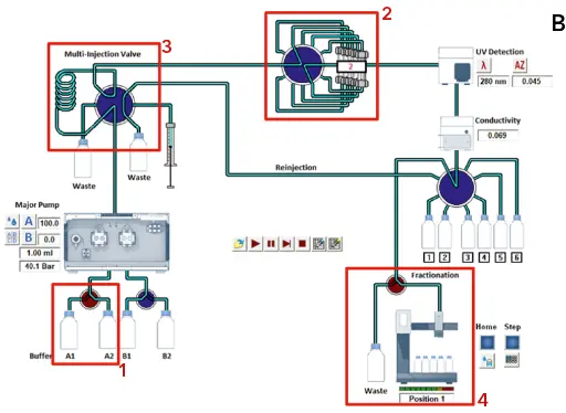
Desalting method. Time control file of desalting method (A). Visualization of AZURA Bio Lab system in basic set up (B).
To run both methods one after the other a sequence table should be used (Fig. 9).

Fig. 9 Sequence table.
Additional devices
Tab. 1 List of additional devices
Device | Description | Article No. |
Outlet valve in an ASM2.2L or stand alone | Smart valve drive with RFID-technology VU 4.1 valve drive for V 4.1 valves, stand alone Universal valve drive for ASM 2.2L, assistant module VU 4.1 for valves V 4.1 Biocompatible multiposition valve with 8 Ports, 1/16“ | AWA01XA |
Filter cartridge | Filter cartridge for pump P 6.1L, high capacity, 2 µm titanium filter, 60 µl volume | A9661 |
Dummy filter cartridge | Empty cartridge, inline filter alternative | A9652 |
Inline filter | Inline Filter, PEEK/Titanium, 1/16“, biocompatible, 10 µm Replacement Frits for inline filter, PEEK/itanium, biocompatible, 10 µm | A3379 A3379-1 |
Column selection valve | Smart valve drive with RFID technology VU 4.1 valve drive for V 4.1 valves, stand alone Biocompatible column selection/sample loop selection valve, for 5 columns/sample loops and 1 bypass, reverse flow, 12 ports, 1/16“, 50 bar | AWA01XA |
Related KNAUER applications
VTN0013 - How to optimize your purification? Your guide for two step purification - principles and system set up
VTN0015 - Two step purification with the sample pump set u
Application details
|
Method |
FPLC |
|
Mode |
IEC |
|
Substances |
n/a |
|
CAS number |
n/a |
|
Version |
Application No.: VTN0014 | Version 1 12/2020 | ©KNAUER Wissenschaftliche Geräte GmbH |

