Science with Passion
Application No.: VTN0032 Version 1 02/2024
Optimize your HPLC-UV system for applications with trifluoroacetic acid (TFA)
J. Menke, C. Schmidt, G. Greco, C. Losch; menke@knauer.net
KNAUER Wissenschaftliche Geräte GmbH, Hegauer Weg 38, 14163 Berlin
Photo: KNAUER
Summary
When using trifluoroacetic acid (TFA) as eluent modifier in liquid chromatography its self-absorption properties can present challenges for baseline stability. As consequence the pumps pulsation, normally less noticeable can become indirectly visible in detector baseline. This can lead to a negative effect on limit of detection (LOD) and limit of quantification (LOQ) for chromatographic methods. Mitigation of this phenomenon can be easily achieved by adjusting the pump mixer volume appropriately.
Introduction
Trifluoroacetic acid (TFA) is commonly used as an ion-pairing agent in High Performance Liquid Chromatography (HPLC). In HPLC, TFA is added to the mobile phase to improve the separation of polar and charged analytes that are difficult to separate using traditional reversed-phase chromatography.
TFA forms ion-pairs with charged analytes, allowing them to be retained on the reversed-phase column for a longer period of time, resulting in improved separation. TFA is particularly useful in the analysis of peptides and proteins, as it can improve peak shape and resolution. However, while TFA is effective as an ion-pairing agent in HPLC, it is important to use it in appropriate concentrations to avoid interfering with the detector signal or causing excessive column wear.
TFA absorbs strongly below 250 nm, wavelengths commonly used by many HPLC-UV applications. This generates interfering signals that result in high background noise and decreased sensitivity, impacting the low limit of detection (LOD) and the low limit of qualification (LOQ). To minimize this interference, TFA is typically used at low concentrations in the range of 0.1–0.5 %. Nevertheless, the effect on the detector baseline can be very noticeable.
Stationary phase interaction of TFA
For better understanding the phenomenon of TFA induced baseline ripple a closer understanding of its stationary phase interaction is necessary. In a typical reversed phase C18 column free silanol groups can become an issue since ion-ion interaction can occur when charged compounds are present. This leads typically to undesired peak shapes since the separation mechanism is now not solely based on polarity. Although a high grade of end-capping can remedy this effect, a residual amount of uncapped free silanols will always be present.
To prevent deprotonation of free silanols, TFA can be used (see Fig. 1). Since it is a strong acid full protonation can be assured. Even when analytes are slightly acidic as well. Since TFA shows ion-ion interaction with the stationary phase it is important to keep in mind, that is retained on the column. Typically, a pH equilibrium is formed on the column, when TFA is used in both eluents.
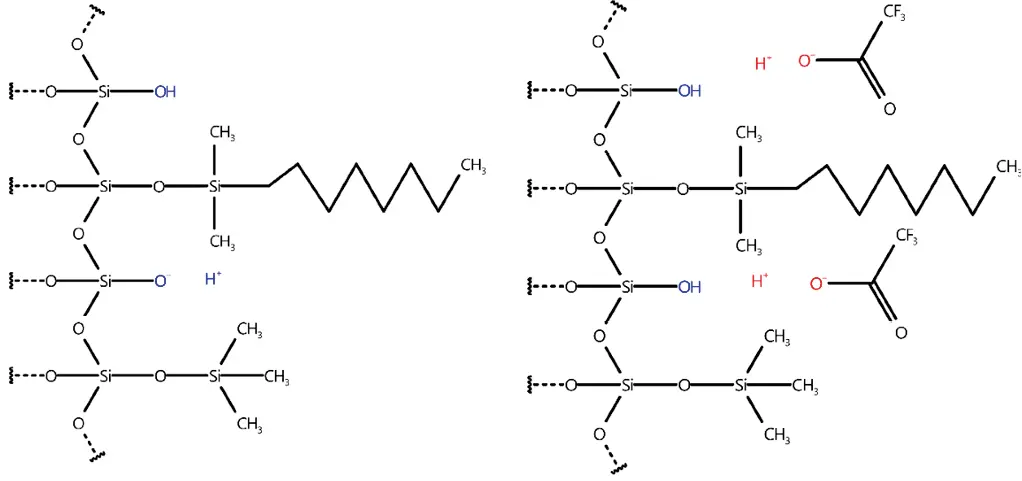
Fig. 1 Left – Free silanol groups (blue), able to deprotonate; Right – silanol groups cannot deprotonate since TFA deprotonated first (red)
Pump influence and incomplete mixing
A high-pressure gradient (HPG) HPLC-pump usually consists of two individual dual-piston pumps that form a binary solvent composition. The pistons move in opposite directions to achieve a constant stream of liquid. To achieve the user set solvent composition, both individual pumps will adjust their speeds to match the overall desired flowrate. For example, in a mixture of 95 % A and 5 % B with a total flow rate of 1 ml/min, pump A would pump 0.95 ml/min, whereas pump B would deliver 0.05 ml/min. Both liquid streams are combined in a mixer for homogenization and further on delivered to the rest of the system. Even in a high-performance LC-pump, the acceleration and deceleration of the pistons and the transfer of delivery between them causes slight flow rate deviations that can be seen as pressure ripple. This effect is called pulsation.
When mixing two liquids that contain TFA, the volume period of one piston is crucial. The volume period refers to the amount of mobile phase that is covered by one pump stroke. When mixing an extreme ratio, such as 95 % A and 5 % B, the B pump’s speed is significantly lower than that of the A pump. If the volume period of one piston becomes larger than the mixer volume, the mixture will be incomplete. This can result in a spike of slightly more or less TFA molecules entering the system, causing a small disturbance in the established pH equilibrium at the stationary phase. This leads to a slight variation in the amount of TFA desorption, which causes the amount of TFA molecules leaving the column to vary as well.
Detection
The variation of TFA is directly visible in a UV-detector measuring at wavelengths below 250 nm. Since TFA absorbs UV light in that spectrum up to 100 times stronger than for example acetonitrile, the disturbance of equilibrium is amplified drastically and becomes visible.
The absorption and desorption spikes of TFA cause positive and negative ripple that add up to a waveform. [1]
Mixing
A strategy to improve a rippled baseline is to improve the mixing capabilities of the pump. An enhanced mixing volume can minimize baseline ripple, although it will increase the gradient delay. [1]
Results
The effect on the baseline noise was evaluated with four different mixers with 100, 200, 400 and 600 µl volumes with a shallow gradient typically used, for example, in peptide analysis. As expected, we observed an improvement of the baseline ripple with larger mixers (see Fig. 2 and Fig. 3). The selection of the mixer size and the flow cell volume of the UV detector needs to be optimized for each application. Generally, smaller mixers guarantee a sufficient mixing performance for most applications, without big impact on the gradient delay volume (GDV) and the run time. In the case of applications with eluents containing TFA, the choice of larger mixers is strongly recommended. The impact of the mixer size on the gradient delay volume can be observed in Fig. 4.
Please note that the absolute amplitude of the ripple is dependent also on the detector and the flow cell.
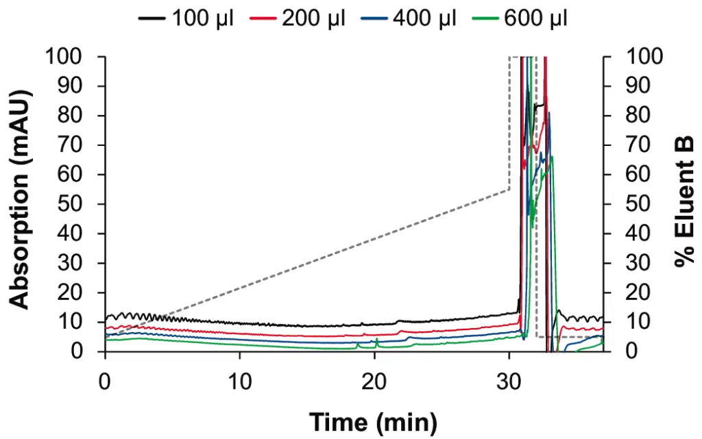
Fig. 2 Staggered overlay of gradients for P 6.1L pump with 100 µl (black), 200 µl (red), 400 µl (blue), 600 µl (green) mixer
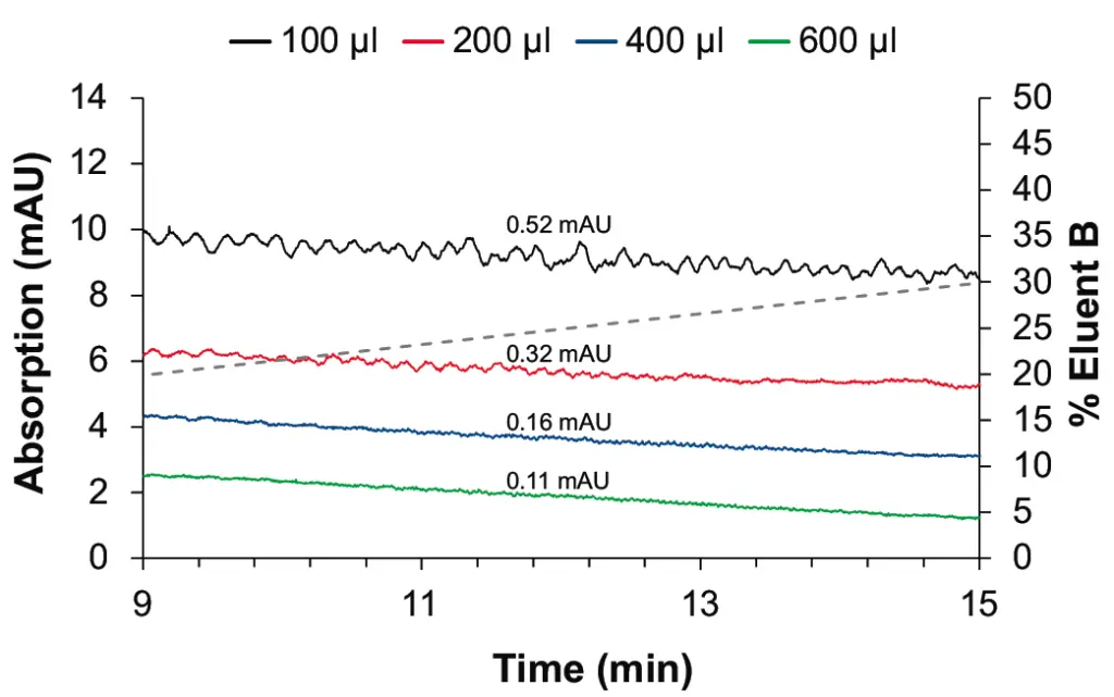
Fig. 3 Zoom on baseline for P 6.1L pump with 100 µl (black), 200 µl (red), 400 µl (blue), 600 µl (green) mixer
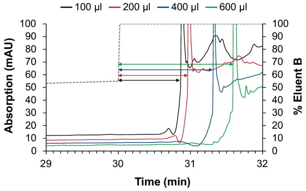
Fig. 4 Effect on gradient delay volume for P 6.1L pump with 100 µl (black), 200 µl (red), 400 µl (blue), 600 µl (green) mixer
Conclusion
When users upgrade from an old 400-bar HPLC system to a modern UHPLC system, they often experience dissatisfaction with the baseline. This is mainly due to the fact that the UHPLC system is optimized to the lowest possible gradient delay volume in order to archive a minimal gradient delay volume. The problem is particularly prevalent when using modifiers like TFA in conjunction with UV detectors.
In order to achieve the most accurate and precise analysis results, it is essential for the user to use a suitable mixer. It is important for the user to consider whether they value obtaining the smoothest possible baseline or the shortest possible analysis time more. Depending on the user’s needs, they must choose the right mixing equipment to optimize the analysis method.
If the user is concerned about the sensitivity of the analysis, and parameters like limit of quantification (LOQ) and limit of detection (LOD) are critical, they should try to select the best possible mixture of the eluent. This can be achieved with the help of modern microfluidic mixers that have the appropriate mixing volume. Microfluidic mixers are designed to facilitate the mixing of fluids that are present in small volumes. They are capable of producing highly homogeneous and reproducible mixtures with a low dead volume.
By utilizing modern microfluidic mixers, the user can achieve optimal mixing conditions and enhance the quality of the analysis results. This will ensure that the analysis method is highly efficient and reliable.
The AZURA® Mixer is an ideal tool for optimizing UHPLC systems for demanding TFA applications.
Material and Methods
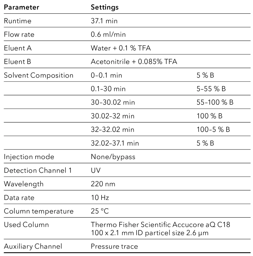
Tab. 1 HPLC Method parameters [2]
Instrument | Description | Article No. |
Pump | AZURA® P 6.1L High Pressure Pump with | |
Autosampler | AZURA® AS 6.1L High pressure analytical HPLC Autosampler | |
Column thermostat | AZURA® CT 2.1L | |
Detector | AZURA® Detector DAD 2.1L | |
Measurement Cell | Standard KNAUER LightGuide UV Flow Cell Cartridge 10 mm path length, 1/16", 2 µl volume, 50 bar | |
Capillaries | AZURA® Analytical K-Connect start-up kit, stainless steel, 1/32" capillaries with fitting sleeves for 1/16"connections 0.1 mm ID | |
Software | ClarityChrom 9.0 | |
Software | ClarityChrom PDA Extension | |
Mixer | AZURA® Mixer, 100µl | |
Mixer | AZURA® Mixer, 200µl | |
Mixer | AZURA® Mixer, 400µl | |
Mixer | AZURA® Mixer, 600µl |
References
[1] Choikhet et al, The Physicochemical Causes of Baseline Disturbances in HPLC, Part I – TFA-Containing Eluents, LCGC Europe (2003)
[2] Strobl et al, TN-72505 (2017)
Application details
Method | HPLC |
Mode | RP |
Substances | Trifluoroacetic acid, TFA |
CAS number | 76-05-1 |
Version | Application No.: VTN0032 | Version 1 3/2024 | ©KNAUER Wissenschaftliche Geräte GmbH |

