
Science with Passion
Application No.: VTN0019 Version 1 08/2021
Reduce pulsation – improve performance and increase longevity of your column using the pulse damper with the AZURA® SEC FPLC System
Ulrike Krop, Florian Glauche, Kate Monks; applications@knauer.net
KNAUER Wissenschaftliche Geräte GmbH, Hegauer Weg 38, 14163 Berlin
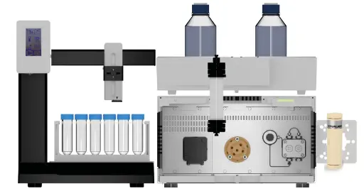
Rendering: KNAUER
Summary
Pressure fluctuations caused by pump pulsation can present a challenge in FPLC, especially when working with the pressure sensitive columns used in size exclusion chromatography applications. Here we analyzed the performance of the KNAUER PEEK pulse damper in combination with the compact pump AZURA P 4.1S. The pulse damper was able to reduce pressure pulsation by up to 92 %. The best working conditions for the pulse damper were determined at small flow rates in combination with a low back pressure within the system. Reducing the degree of pressure pulsation prevents potential damage to the column packing and therefore it is highly recommended to include the pulse damper within the flow path of the AZURA SEC FPLC system. Here, two system configurations are reviewed in detail.
Introduction
Piston pumps are the standard solution for buffer delivery in FPLC systems. Although they are very reliable and require low-maintenance, residual pulsation cannot be fully prevented. Some applications such as size exclusion chromatography (SEC), which aim for high resolution fractionation, are highly sensitive to the pump’s residual pulsation. The typical characteristics of SEC are the use of an isocratic method and columns that are packed with relatively small particles, which create a backpressure that often limits the flow rate. As SEC is a non-binding method, only driven by the diffusion of the molecules into the pores of the resin, the column packing is of particular importance for a good separation.
A stable pressure is not only crucial for a stable UV baseline but more importantly for the life span of both the column and the packing. Due to their low-pressure limit, many expensive SEC columns are highly prone to damage of the column bed caused by pressure pulsation. Our AZURA SEC FPLC System is the ideal system for simple SEC applications. The system is equipped with an isocratic, cost-attractive P4.1S pump. Since this pump type is not equipped with an active pulsation compensation, the addition of a pulse damper to the system can be used to improve the baseline and minimize pressure impulses. The KNAUER PEEK pulse damper combines high damping performance with a reliable, membrane-free assembly and can be easily integrated into AZURA FPLC systems. In this study, a biocompatible pulse damper was analyzed for its ability to reduce pressure pulsation of the biocompatible P4.1S and therefore protect pressure-sensitive columns.
Results
Testing of KNAUER PEEK pulse damper
The pulsation of the isocratic P4.1S was compared with and without the use of the PEEK pulse damper. The relative reduction of pulsation for different flow rates and different back pressures are listed in Tab. 1 and additionally depicted in Fig. 1. A maximum reduction of 92 % was reached at a flowrate of 0.1 ml/min and a back pressure of ~1.5 bar. At a back pressure of ~1.5 bar, the highest relative reduction of pulsation was found between 0.1 and 5 ml/min.
Fig. 2 illustrates the effect of the pulse damper on three external pressure signals with and without a pulse damper at different flowrates with ~1.5 bar back pressure. To function correctly the KNAUER pulse damper needs a backpressure of at least 1-2 bar (data without backpressure not shown). Working conditions of the P 4.1S with a back pressure of ~10 bar reduced the pulsation of the pump and therefore, as a consequence, the effect of the pulse damper. Small flow rates in combination with a low back pressure provided the highest reduction of pulsation using the pulse damper; for this reason the pulse damper is especially recommended for systems and applications using these working conditions.
Percent reduction of the pulsation/amplitude for different flow rates and different back pressure with water
Flow rate (ml/min) | ~ Back pressure (bar) | Reduction of pulsation/ |
0.05 | 1.5 | 87 |
0.05 | 4.5 | 63 |
0.05 | 10 | 89 |
0.1 | 1.5 | 92 |
0.1 | 4.5 | 86 |
0.1 | 10 | 84 |
0.5 | 1.5 | 83 |
0.5 | 4.5 | 60 |
0.5 | 10 | 45 |
1 | 1.5 | 81 |
1 | 4.5 | 35 |
1 | 10 | 2 |
5 | 1.5 | 61 |
5 | 4.5 | 31 |
5 | 10 | 8 |
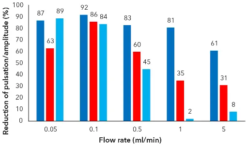
Fig. 1 Comparison of the percent reduction of the pulsation/amplitude for different flow rates and different back pressure (dark blue) ~1.5 bar; (red) ~4.5 bar; light blue ~10 bar with water
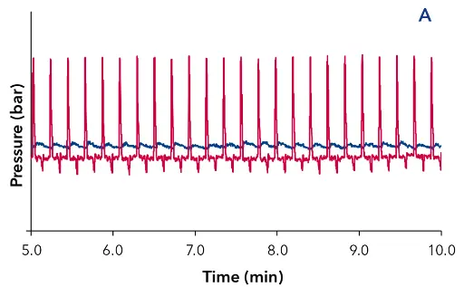
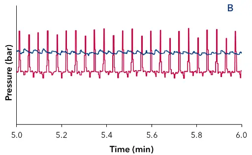
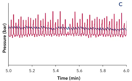
Fig. 2 Overlay of the external pressure signal at different flowrates, approx. 1.5 bar back pressure and water as eluent. Pressure signal without pulse damper (red), pressure signal with pulse damper (blue); (A) 0.1 ml/min;
The pulse damper showed the highest damping efficiency for small flow rates in combination with a low back pressure and is especially recommended for the AZURA SEC FPLC System. Here we will discuss the two possible system set ups. These points are as well summarized in Tab. 2.
Overview of the system set up options for the pulse damper installation sites and their benefits and limitations.
Installation site of | Behind the | Before the pressure |
Benefits |
|
|
|
| |
| ||
Limitations |
|
|
Recommendations | For application and/or columns with a back pressure above 2–3 bar | For application and/or columns with very low back pressure (below 2–3 bar) |

Fig. 3 Flow scheme of AZURA SEC FPLC System with pulse damper behind the pressure sensor
The first, and simplest, configuration is to place the pulse damper behind the pressure sensor of the pump. The flow scheme and the system’s set up with the capillary connections is shown in Fig. 3 and Fig. 4. The advantage here is that only one backpressure regulator is used and the maximum pressure function of the pump is not affected, meaning that if a blockage occurs behind the pump head the pump will automatically stop when the pressure limit is reached. The drawback is that no extra back pressure can be applied to improve the pump performance and pulsation. This configuration is best used for applications with a higher back pressure created by the column.
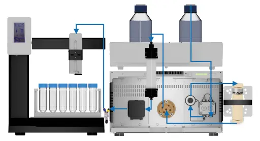
Fig. 4 System set up of AZURA SEC FPLC System with pulse damper installed behind the pressure sensor
The second option is to place the pulse damper between the pump head and pressure sensor of the P4.1S pump and to install an additional back pressure regulator. The flow scheme and the system setup with the capillary connections is shown in Fig. 5 and Fig. 6.
The backpressure regulator should be adjusted to approximately 10 bar at the working flow rate. The additional back pressure increases the performance of the pump. However, due to its placement, it will not be detected by the pressure sensor. The drawback is that a possible blockage of the pulse damper or the backpressure regulator can therefore not be detected by the pressure sensor, which may lead to pump head damage. A second back pressure regulator behind the detector outlet is still recommended to prevent air bubbles during detection. This configuration is recommended for applications and columns with a very low back pressure (below approximately 3 bar).

Fig. 5 Flow scheme of AZURA SEC FPLC System with pulse damper and additional back pressure regulator installed before the pressure sensor
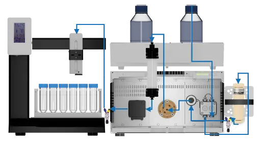
Fig. 6 System set up of AZURA SEC FPLC System with pulse damper and additional back pressure regulator installed before the pressure sensor
Conclusion
The KNAUER PEEK pulse damper is effective in dampening the residual pulsation from the P4.1S system pump by up to 92 %. This results in very low-pressure fluctuation and baseline noise. The best damping results were achieved when running FPLC using low flow rates and back pressure. We advise the installation of the pulse damper in the AZURA SEC FPLC system flow path to reduce pulsation, improve performance and protect pressure sensitive column. Two installations sites in the AZURA SEC FPLC system are possible. Their benefits and limitations were discussed.
Materials and Methods
The pressure measurements were performed using an external pressure sensor. The pulse damper was installed behind the pump, followed by the external pressure sensor and a back pressure regulator. Testing was performed with various back pressure (w/o back pressure; approx. 1.5 bar; approx. 4.5 bar and approx. 10 bar). The following flow rates were tested: 0.05; 0.1; 0.5; 1 and 5 ml/min. The pressure signal of the external pressure sensor was recorded for 15 minutes. In addition, the flow was monitored with a flowmeter. The mean pressure was determined over a period of 10 minutes. The amplitude/pulsation was obtained from the difference of the max/min value over a period of 10 minutes. The relative reduction of the pulsation/amplitude was set in relation to the mean pressure value.
Method parameters for the analysis of pulsation
Method parameter | |
Eluent (A) | Water or 90/10 Water/Ethanol |
Flow rate | 0.05; 0.1; 0.5; 1 or 5 ml/min |
Back pressure | w/o, ~1.5; ~4.5 or ~10 bar |
Detection | External pressure sensor, flowmeter |
Data rate | 20 ms/50 Hz |
Temperature | RT |
Recommended system set up for the AZURA SEC FPLC System: Article No.: SYS872101122
Instrument | Description | Article No. |
AZURA Assistant ASM 2.2L | Left module: UV detector UVD 2.1S – EDA03XA Middle module: Valve drive VU 4.1 – EWA04 Right module: Pump P 4.1S, 50 bar, 10 ml, ceramic – DPG12EB | |
UV Flow cell | Semi-preparative bio-compatible 3 mm | |
AZURA V 4.1 Valve | Multi-injection valve, biocompatible, | |
Pulse damper | Pulse Damper, High Volume, PEEK | |
Back pressure regulator | Back-Pressure Regulator 1-20 bar | A70087 |
Fraction Collector | Foxy R1 for 1/16'' or 1/8'' tubing | |
Software | Purity Chrom basic |
System and devices used for the analysis of pulsation of the pressure signal.
Instrument | Description | Article No. |
Pump | Pump P 4.1S, 50 bar, 10 ml, ceramic, with pressure sensor | |
External pressure sensor | Biocompatible Pressure Sensor | |
IFU Box | Interface Box IFU 2.1 LAN, 4 channels LAN connection, including accessories | |
Distribution Box | Distribution Box 24 V for auxiliary equipment power supply 24 V for up to 6 peripheral devices | |
Pulse damper | Pulse Damper, High Volume, PEEK | |
Back pressure regulator | Back-Pressure Regulator 1–20 bar | A70087 |
Flowmeter | Mini CORI-Flow (M13) Mass flow meter/controller, 1–50 ml/min | |
Flowmeter | Mini CORI-Flow (M12) Mass flow meter/controller, 0.03–3.3 ml/min | |
Software | Purity Chrom basic |
Related KNAUER Applications
VTN0002 – Performance evaluation of KNAUER pulse dampers in comparison to competitive dampers
Application details
|
Method |
FPLC |
|
Mode |
SEC |
|
Substances |
n/a |
|
CAS number |
n/a |
|
Version |
Application No.: VTN0019 | Version 1 08/2021 | ©KNAUER Wissenschaftliche Geräte GmbH |


