
Science with Passion
Application No.: VTN0030 Version 1 08/2023
No more compromise – preparative LC systems for purifications with high flow and high back pressure
Y. Krauke, A. Dürasch, G. Greco; krauke@knauer.net
KNAUER Wissenschaftliche Geräte GmbH, Hegauer Weg 38, 14163 Berlin
Collage: KNAUER
Summary
The purification of target compounds by preparative liquid chromatography at high flow rates with small silica gel particles is challenging for most preparative systems due to the resulting high back pressure. Here, a special preparative system setup is presented that enables the purification and fractionation of target substances at flow rates of up to 800 ml/min with a max. back pressure of up to 100 bar.
Introduction
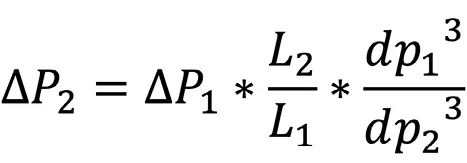
Preparative HPLC purifies target compounds from a sample solution. The amount of purified compound per run can vary between few milligrams to several grams in laboratory scale. The typical workflow is to develop first a small, analytical scale purification method which is then scaled-up to the desired size. For the purification of fine chemicals as in the pharmaceutical industry high purities are desired and, therefore, the particle size of the used column material is kept small to ensure a high resolution of the peaks. Usually, particles of 10 µm are used but these small preparative particles generate higher back pressure then larger particles of i.e. 15 µm or 20 µm. The back pressure generated by columns with particles > 10 µm are neglectable in analytical scale as typical analytical pumps have usually high maximum pressure of at least 700 bar. Preparative pumps have lower maximum pressure as analytical pumps and in general the higher the flow rate is, the lower is the maximum pressure. For example, a KNAUER preparative AZURA® P 2.1L with 100 ml/min pump head has a maximum pressure of 400 bar, whereas a P 2.1L with 1 000 ml/min has a maximum pressure of 50 bar. These facts must be considered during the scale-up process, especially in reversed phase (RP) mode as the used solvents (i.e. acetonitrile/water) generate higher back pressure then typical normal phase (NP) solvents (i.e. heptane/isopropanol). The expected back pressure (ΔP2) of the larger column can be calculated using the Darcy law equation (Formula 1) with L – column length, dp – diameter particles:
In the case of a linear scale-up, only the column diameter is increased and the column back pressure does not change. Consequently, the expected back pressure of the column can already be determined in analytical scale. It is important to determine the system pressure to have an accurate prediction. Until now, a compromise had to be made for methods with high flow rates or high back pressure, either reducing the flow rate at the expense of time or increasing the particle size sacrificing resolution. To overcome this problem a preparative high-pressure gradient (HPG) system is presented that enables flow rates of 800 ml/min with a maximum pressure of 100 bar.
Sample Preparation
Acetonitrile was supplemented with 0.1 % of acetone as tracer for the gradient.
Results
The major gradient pump of the high flow preparative system consists of four 500 ml/min P 2.1L pumps which are organized in two pairs. Pump A1 and pump A2 operate together as pump A. The same applies to pump B (B1 & B2). Pump A and Pump B can generate gradients of up to 800 ml/min (maximum recommended flow rate) at a max. pressure of 100 bar (Fig. 1). The feed is directly injected by a 250 ml/min pump with a ternary gradient block that allows connection of three different solutions, for example a feed, cleaning solvent and washing solvent.
The UV measuring cell is placed directly behind the column outlet and is connected via fibre optic cables to the multi wavelength detector.
Collection of the target fractions is carried out by two multi-position valves. The first valve selects between waste and fraction, and the second between the different fractions (Fig. 1 V2, V3).
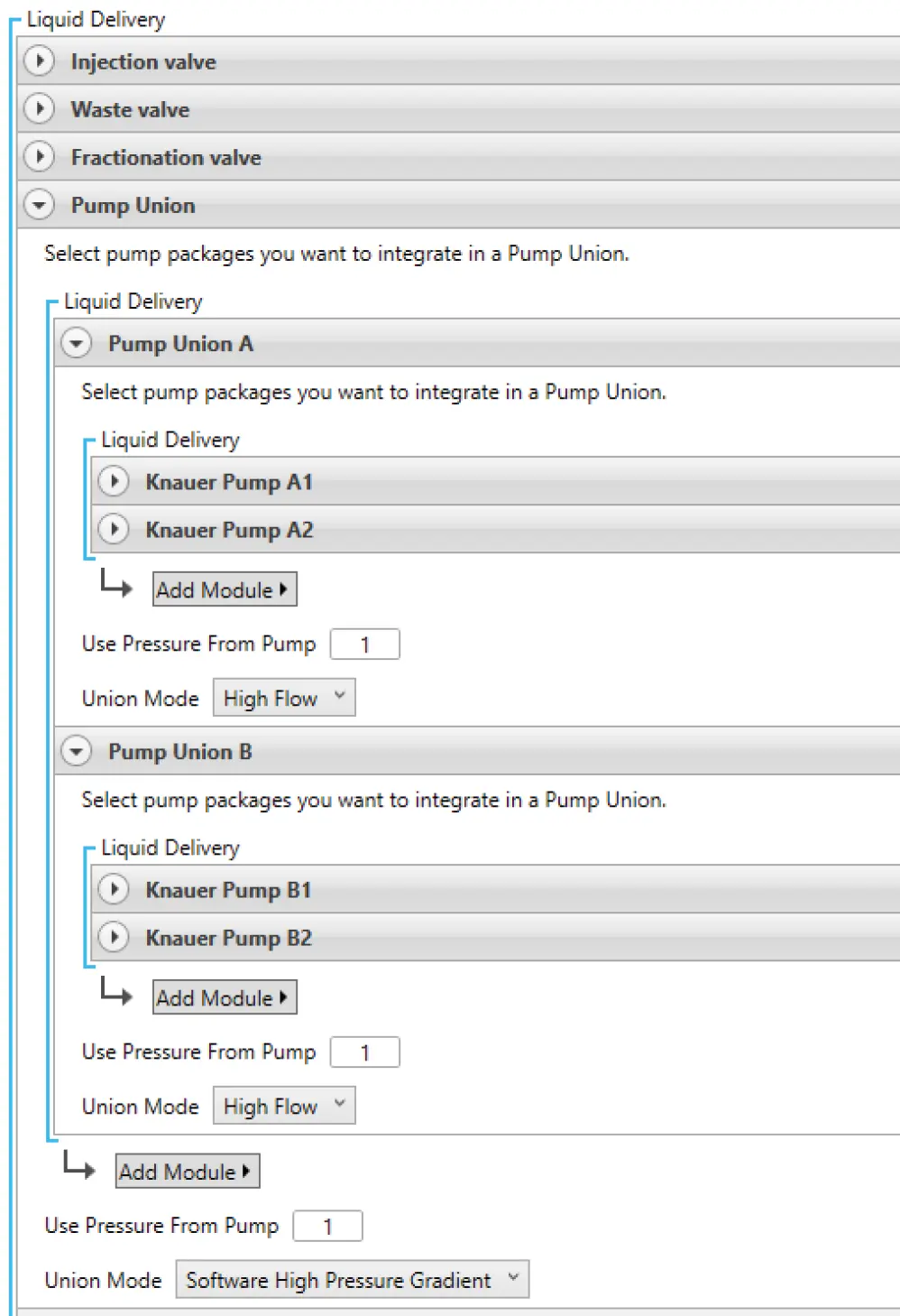
The switching of valves generates a back pressure as the solvent stream pressures against the valve sealing during the switching process. Higher flow rates, lead to higher back pressure. At the applied flow rate of 700 ml/ min the back pressure from switching would be too high and exceed the maximum pressure of the system. Therefore, the KNAUER multi-position break-free valves were used in this system at position V2 and V3. A special design of the valve allows valve switching without any significant back pressure (Fig. 4 and Fig. 5). The pump setup as described before is enabled throughout a configuration feature in the software PurityChrom called “Pump Union” (Fig. 2A). The information of the flow rate for i.e., channel A is split into the two connected pumps. If channel A should deliver 700 ml/min, each pump will pump 350 ml/min.
The total flow of the major pump/pump union, the gradient and split for each pump is shown in the visualisation window of the PurityChrom® 6 software (Fig. 2B). The pump union is integrated in the visualisation of the system in PurityChrom® 6 (Fig. 3).
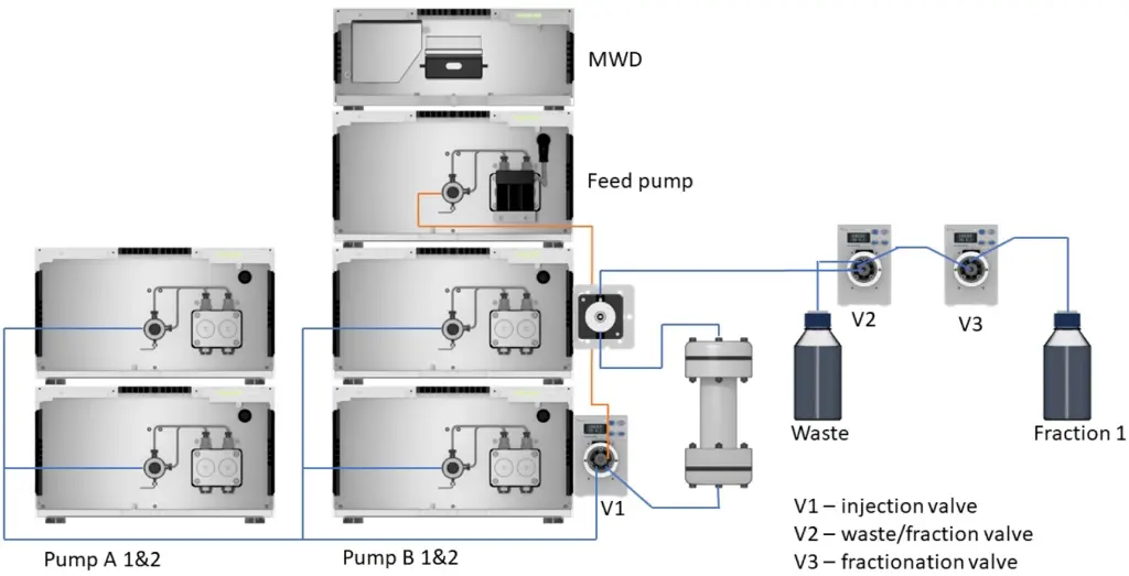
Fig. 1 Set-up high flow preparative system for 800 ml/min with max. pressure 100 bar
A)
B)
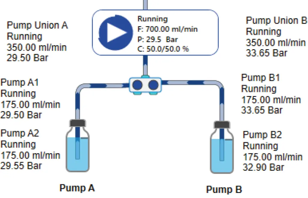
Fig. 2 A) Definition of “pump union” in the configuration of PurityChrom® 6, B) “pump union” in the visualisation depiction of PurityChrom® 6 with the flow rates and pressure of each pump
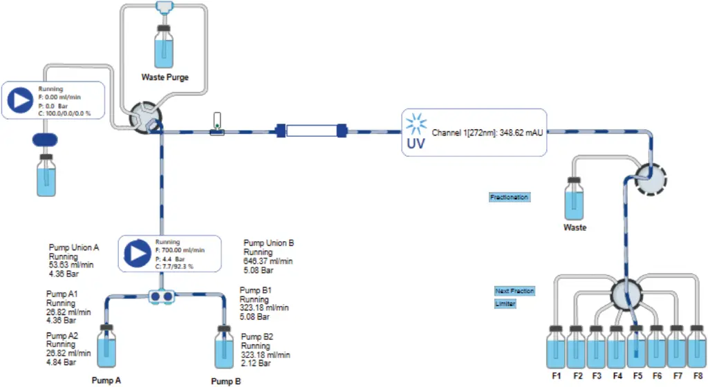
Fig. 3 Visualisation of high flow preparative system in PurityChrom® 6 software
In a first experiment, the system pressure of the high flow system was measured over a gradient from 0 to 100 % B (Acetonitrile). Acetone was added as tracer to the acetonitrile in channel B and the absorption was recorded at 272 nm. To show the low back pressure from switching of the break-free valve, five fractions were taken starting from 1 min before switching back to waste at 6 min. The system back pressure was approx. 7 bar at 100 % water and decreased with increasing acetonitrile concentration to approx. 4.5 bar. No distinct pressure spikes were detected during fractionation (Fig. 4).
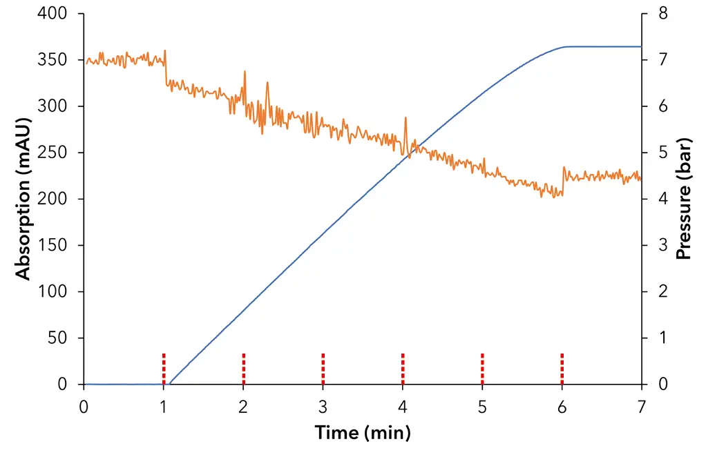
Fig. 4 System back pressure in dependence of acetonitrile gradient from 0–100 % ACN without back pressure regulator; orange – system back pressure, blue – ACN + 0.1 % acetone trace; red – dashed lines – switching fraction valve; 272 nm; 700 ml/min
The experiment was repeated with the same system set-up and an additional back pressure regulator was placed between injection valve and detector and set to a pressure of approx. 85 bar (Fig. 5) simulating a column.
The back pressure remained stable at approx. 85 bar and no pressure spikes during the switching of the fractionation valve were observed (Fig. 5).
The gradient measured by the absorption of acetone was in both experiments steady showing that the gradient composition of the pump union was working as set (Fig. 4 and Fig. 5).
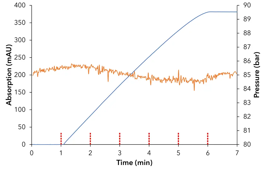
Fig. 5 System back pressure in dependence of acetonitrile gradient from 0–100 % ACN with back pressure regulator set to approx. 80 bar; orange – system back pressure, blue – ACN + 0.1 % acetone trace; red – dashed lines – switching fraction valve; 272 nm; 700 ml/min
Conclusion
The presented high flow preparative HPG system enables flow rates of up to 800 ml/min with a maximum back pressure of 100 bar. The PurityChrom® 6 software enables to setup a HPG pump out of multiple pumps. Here, a binary gradient was formed of four pumps. Channel A as well as channel B were formed of two pumps each. The flow for each channel is split into the two corresponding pumps. Two KNAUER break-free multi-position valves are integrated for fractionation of the target substances. Using standard valves rotation of the valve during fractionation would generate a high back pressure especially at high flow rates. In the worst case the maximal pressure of the pump is reached, which in turn results in the emergency stop of the system. This issue is solved using the KNAUER break-free valves and even at 700 ml/min no distinct pressure spikes generated by the valves were observed.
The combination of the high flow preparative pump setup using the pump union tool and the break-free valves allows purification of fine chemicals at high flow rates using columns with smaller particles.
Material and Methods
Tab. 1 Instrument set-up
Instrument | Description | Article No. |
Pump A1 | AZURA P 2.1L, 500 ml, sst | |
Pump A2 | AZURA P 2.1L, 500 ml, sst | |
Pump B1 | AZURA P 2.1L, 500 ml, sst | |
Pump B2 | AZURA P 2.1L, 500 ml, sst | |
Pump head inlet (4x) | ||
Feed pump | AZURA P 2.1L, 250 ml, sst | |
AZURA LPG ternary module | ||
Detector | AZURA MWD 2.1L | |
Flow cell | Preparative UV flow cell, fibre optic version, 1/8" | |
Fibre optics adapter kit | ||
Valve – Inject | AZURA Valve Unifier VU 4.1 | |
2-position valve, 6 port, sst, 1/8" | ||
Mounting bracket | ||
Valve – Waste/Fraction | AZURA Valve Unifier VU 4.1 | |
Break-free MPOS valve, sst | ||
Valve – Fractionation | AZURA Valve Unifier VU 4.1 | |
Break-free MPOS valve, sst | ||
In-line check valve | Swagelok Stainless Steel Poppet Check, 1.8 bar opening pressure, 1/8" | |
Capillaries | PEEK – capillaries ID 2.0 mm, 1/8" | |
Software | PurityChrom® 6 Full License |
Tab. 2 Preparative method parameters 700 ml/min
Parameter | Description | ||
Eluent A | H2Odd | ||
Eluent B | ACN + 0.1 % acetone | ||
Flow rate | 700 ml/min (A/B) | ||
Temperature | RT | ||
Gradient | Time [min] | % A | % B |
0.00 | 100 | 0 | |
1.00 | 100 | ||
6.00 | 0 | 100 | |
7.00 | 0 | 100 | |
Detection UV | 272 nm | ||
Data rate UV | 2 Hz | ||
Time constant UV | 0.50 s | ||
Autozero | At 0.00 min |
Application details
Method | Preparative HPLC |
Mode | Other |
Version | Application No.: VTN0030 | Version 1 08/2023 | ©KNAUER Wissenschaftliche Geräte GmbH |

